ME 210 · Winter 2026 · Stanford University
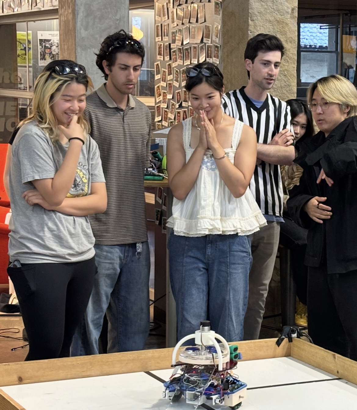
Turty Droid
An autonomous puck-shooting robot powered by ultrasonic navigation,
proportional-derivative (PD) wall-following, and encoder-controlled
precision firing.